Inhaltsverzeichnis
Overview and Structure of SIGMA
Overview and Structure of SIGMA
After starting SIGMA the application presents itself as shown on the left side in the figure. A frame, which has the same structure as the windows explorer is located on the left side of the start-up window and shows information about the current project. This area is titled Project data and it is shown in detail on the right hand side of the figure. In this frame the most important data of the calculation are clearly arranged.
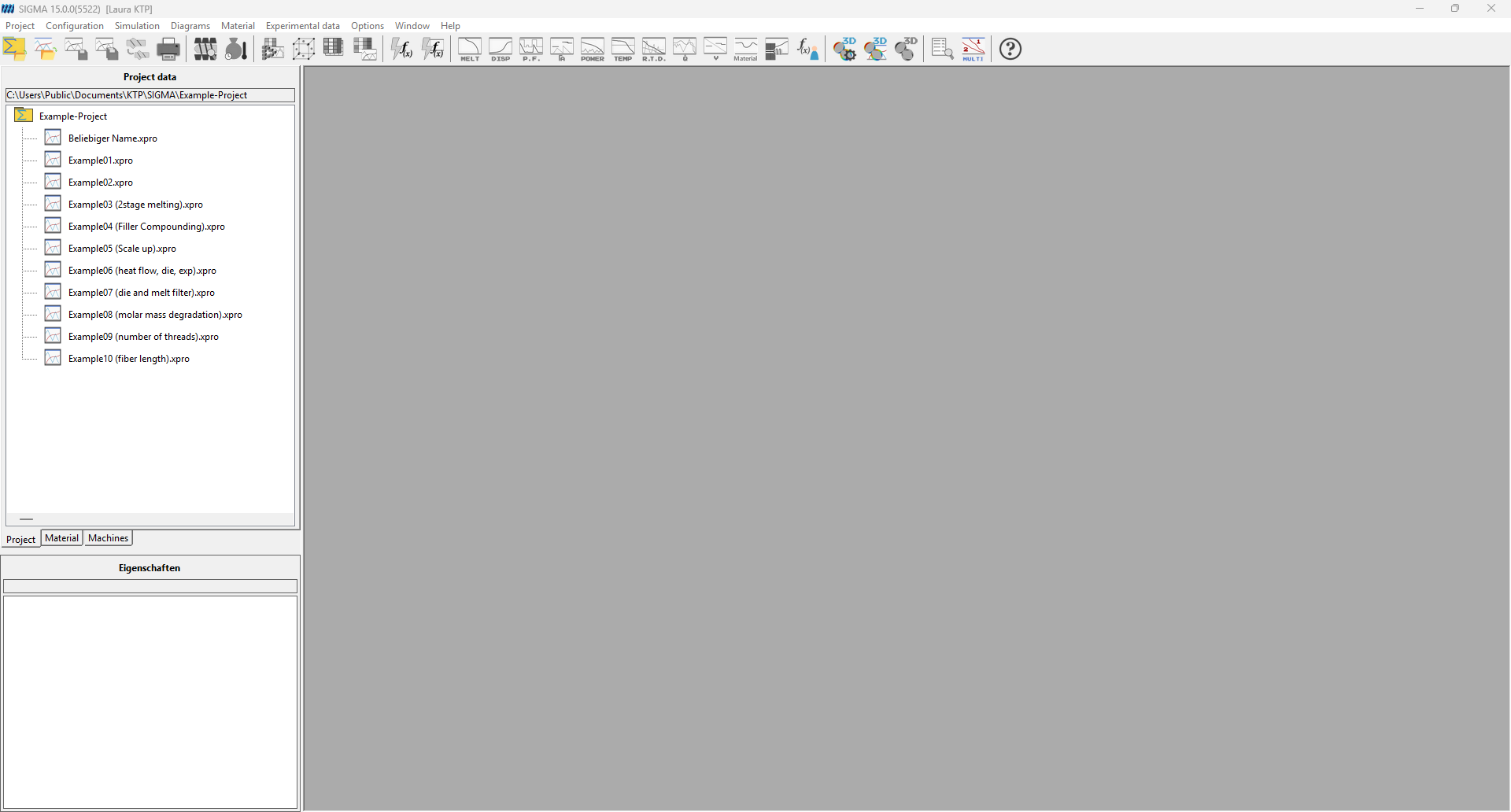 Figure: User interface
Project Data
A SIGMA Project (Chapter Project) is used to manage the different files which are created and needed by SIGMA. A project is a folder in the directory. Essentially it contains various processes.
A SIGMA Process (Chapter Process) is the basic unit to work and simulate with. It unites all required data. The most important components are:
- Machine configuration (Chapter Enter Machine Parameters and Configuration ): The machine configuration manages the characteristic properties of a concrete machine and all its elements.
- Barrel configuration (Chapter Define Barrel Elements): The barrel configuration defines a concrete configuration for a barrel consisting of the defined barrel elements for this process.
- Screw configuration (Chapter Screw Elements): The screw configuration defines a concrete configuration for a screw consisting of the defined screw elements for this process.
- Process parameters (Chapter Simulation) and Material data (Chapter Material Data): The process parameters define the barrel temperatures and the material stages. But the concrete material data are saved in separate files so they are not integrated part of the process parameters.
- Die configuration (Chapter Die Module): If a die is assigned to the process, SIGMA can calculate the pressure at the screw tip.
These items listed above are not integrated parts of a process but they are saved in separate files which are independent of each other. In this way it is possible to use the same machine configuration in different processes. All example processes use the machine example.mas for instance.
This structure can be found in the project explorer, see figure. Additionally, there are listed the items Calculation settings (Chapter Calculation), Results (Chapter Options), and Experimental data (Chapter Experimental Data Management). The items machine configuration, barrel configuration and screw configuration are grouped into the item machine.
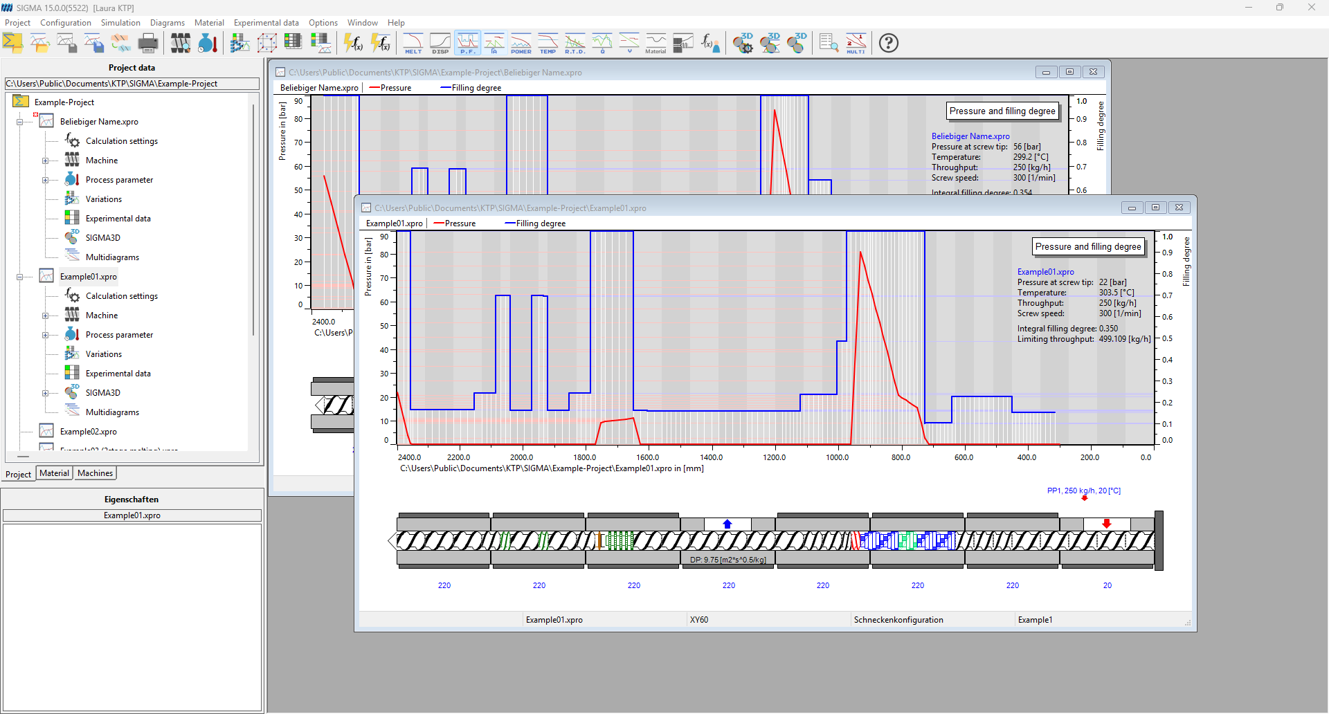
Figure: User interface project
When double clicking on an item in the project explorer, a corresponding window opens up, which shows the characteristic data and allows modifying them. The machine, barrel and screw configuration can either be edited directly by clicking on the respective name or icon in the project explorer or in the dialog Visual machine configuration (Chapter Enter Machine Parameters and Configuration). This gives an overview of screw, barrel and machine and opens up when clicking on Machine or choosing Configuration, Configuration editor within the main menu. This way of changing data which are relevant to the calculation leads to a loss of the current results and the modified settings are available for a new calculation. If data are changed this way and therefore no longer correspond to the original data in the saved files, the unsaved items are marked with an asterisk (*). An exclamation mark marks faulty data. The corresponding data should be checked before the next calculation.
Process Window
By activating a process, a window that contains all information about the results of this process opens up within the empty space. The figure shows two of such Process windows. The process window is divided into two parts. A diagram with the current calculation results (Chapter Diagrams ) which depends on the selection made is placed above the second part a picture of the screw and the barrel configuration. Additionally process parameters (barrel temperatures and material stages) are given in textual form. So far as they are available also the experimental data (Chapter 9) are shown.
SIGMA also allows to define so-called Batch processes (Chapter Create a Batch Process), which are like normal processes but they use one machine configuration with several varying process parameters. In case of a batch process the process window shows the process parameters of the base process and a graph for each variation in the diagram.
If the cursor points at the values for the barrel temperatures or material stages placed in the picture of the machine configuration in the lower part of the window they change into hyperlinks. By clicking on them a window opens up where it is possible to change the barrel temperatures or material stages.
If the cursor points at the graphs in the diagram the calculation results and experimental data at the cursor position are shown in the properties frame, placed in the lower left below the project data.
Material Data
The upper left frame contains besides the project data tab a tab called Material. The material data are fundamental for each calculation and therefore they should be measured and inserted very carefully. SIGMA offers the direct access to the relational database of PAM. PAM is a part of the SIGMA distribution and assists polymer engineers in administrating material data of polymers and in evaluating material parameters of series of measurements.
The material tab itself is divided into two frames (see figure right) which show the materials (Chapter polymers, polymer blends, and filled polymers) contained in the connected database (above) and in the current project folder (below). The default database can be changed under Options (Chapter Options).
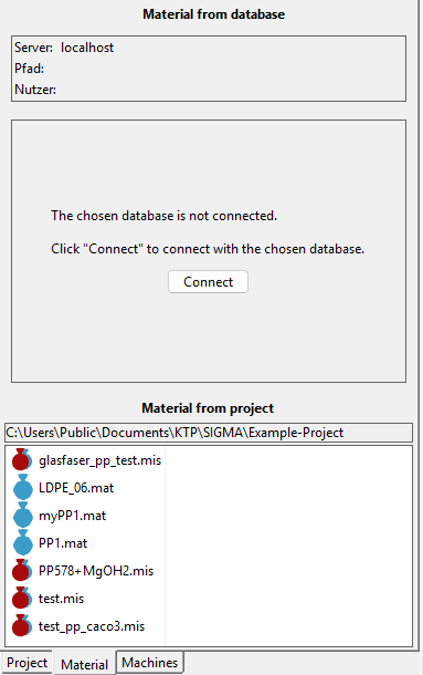
Figure: User interface material
If there is no database specified, a button that opens up the connect database window is available (see figure left). In this way it is possible to connect with any database. Double clicking on a material opens up the Material data window where it is possible to change the material properties. Note that there is no Ok-button. But the changes can be saved to the material or database file. To change the material data of the current process without saving the changes to the material or database file the material data window must be opened up by double clicking on the material in the project tab and confirmed by the Ok-button.
A right click on one of the material lists opens up a menu that simplifies creating, changing, and deleting materials of the project folder or database. The menu also comprises items to update the lists if they were edited from the outside as well as a function to export material data files to another folder.
Machine Data
The third tab is named Machines and the bottom part contains the project’s machines, screw and barrel configurations (see figure). Double clicking a machine or configuration name on this tab opens the respective editor’s windows. The upper part of the tab contains an optional machine database. Choose Options, Database for a default database; hit Connect on the Machines tab or choose Configuration, Connect to database to select a database and connect it like described in chapter Options. In contrast to the material data there is no predefined machine database. To create a machine database choose Configuration, Create database within the main menu. The window Create machine database opens up (see figure). Enter path and name by hitting the … button. Connect as ”SYSDBA” with Password ”masterkey” (cf. chapter Options) and contact your administrator if the connection fails.
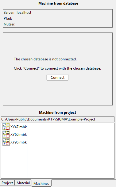 Figure: Tab machines
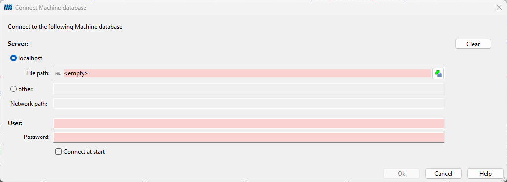
Figure: Connect material database
Properties
The Properties frame is located below the project and material tabs. According to the current selection in the project explorer or the material lists the frame shows the characteristics of this item. In case of a process the characteristics are the files the process is based on. In case of machine elements or materials all input data are shown up.
Besides this static data the properties frame displays the calculated results for the cursor position on a diagram in the process window.