Dies ist eine alte Version des Dokuments!
Scale-Up Module
The scale-up module serves for the transfer of processes to machines with larger and smaller diameters respectively. Starting from a so called model process, the geometry of the master design and the respective process parameters are calculated on the basis of transfer rules. The starting point of the scale-up is a user-defined complete process. A scale-up of processes with more than one feeding barrel is possible with SIGMA.
Selection of the Target Machine
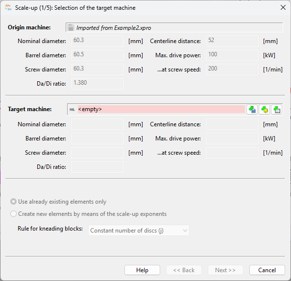
The Scale-up button opens the dialogue box shown in the illustration. The upper part of this box displays the machine data for the output process. An Explorer window allows you to select the machine to which the current process is to be transferred.
The procedure for selecting the elements is defined in the lower third of the dialogue box. The default setting is ‘Use existing elements only’. This ensures that only the screw and cylinder elements stored in the element library are used. With this procedure, the quality of the transfer depends heavily on the number of elements available in the library.
Alternatively, SIGMA 7 can generate fictitious elements that meet the requirements of similarity theory. This provides the optimal transfer result from a similarity theory perspective. By comparing the simulation results of both procedures, the influence of individual elements on the process can be better assessed.
In the latter case, the generation of screw and cylinder elements, it may also be necessary to select a transfer rule for the kneading blocks. This is always necessary when the model and main designs have different L/D ratios. There are three options to choose from:
- Equal number of kneading discs in main and model machine
- Constant staggering angle α
- Constant staggering angle and constant number of discs
Especially energy input, melting behavior, and degree of mixing are strongly influenced by the chosen law. The results have to be evaluated by the user for the unique process.
Setting of the Exponents
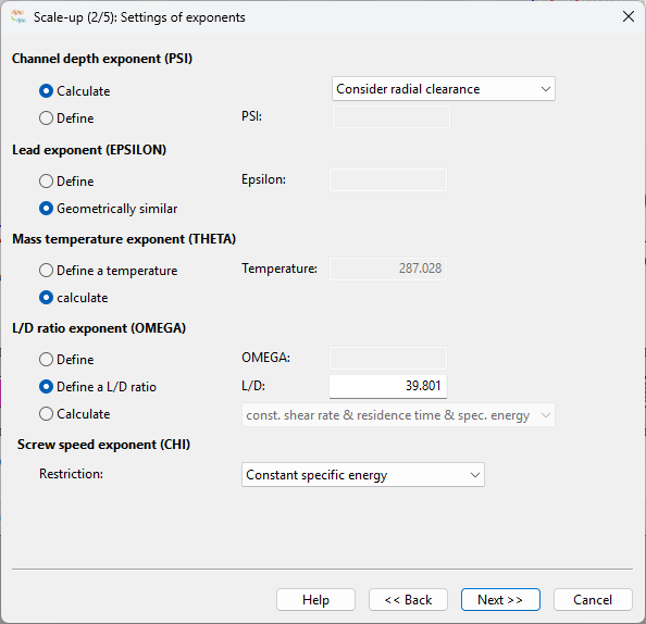
After the activation of the Next button, the boundary conditions and the defaults for the transfer can be determined (see figure). The screw length to diameter ratio (L/D) and the boundary conditions are of particular importance for the transfer of the operating point.
Some options presented in the figure. are of experimental character. This especially concerns the exponents for lead and mass temperature. Normally, presetting should fit here. Nevertheless, a change of the mass temperature exponent and of the lead exponent is possible in SIGMA 7. Through this, the user is provided with the opportunity to assess the influence of individual geometry values on the process and to influence the simulation result by adjusting it. It has to be taken into consideration, however, that doing this is always connected with a violation of similarity theoretical assumptions.
As shown in the basics handbook, the channel depth exponent is calculated from the geometrical data of the chosen machines. The radial clearance can be considered or not in SIGMA 6. This will take direct effect on the mass flow rate and screw speed of the target machine.
SIGMA suggests keeping the L/D ratio constant for model and main machine. However the user is allowed to define an L/D ratio for the target machine. Thereby, the machine is automatically trimmed to the required length.
Furthermore it is possible to calculate a recommended L/D ratio by choosing ”Calculate”. In this case the conditions constant shear rate and constant residence time are fulfilled at the same time.
By defining an L/D ratio or using the presetting, there are five scale-up boundary conditions available in SIGMA. These are:
- Constant specific energy input
- Constant heat flow density
- Constant shear rate
- Constant barrel temperature
- Constant residence time
Among other things, the choice of the boundary condition has considerable influence on the screw speed as well as the throughput. Both are functions of the channel depth exponent, for this reason the evaluation must be done for the unique process.
With a rising throughput, however, the requirements on the heat transfer also increase. In this way, higher temperature inhomogeneity in the melt evolves and, possibly, a non-negligible increase of the melt temperature occurs.
Calculation of the Exponents
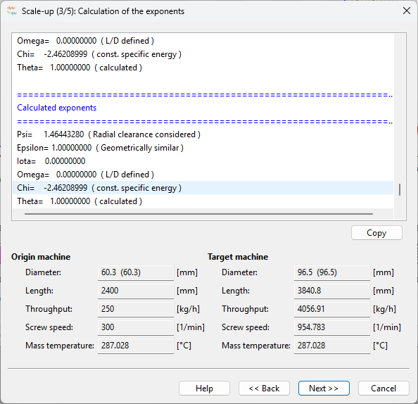
By activating the Next button an iterative calculation of the model law exponents is carried out. On the basis of these exponents, at first the process parameters are calculated and illustrated in the dialog (see figure).
Calculation of Screw and Barrel Configurations
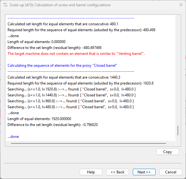
Subsequently, the screw and the barrel are generated. While applying the elements of the construction kit, the quality of the generated process generally increases with the amount of different elements.
All steps carried out during the configuration of the screw and the barrel can be reproduced by means of the dialog window (see figure).
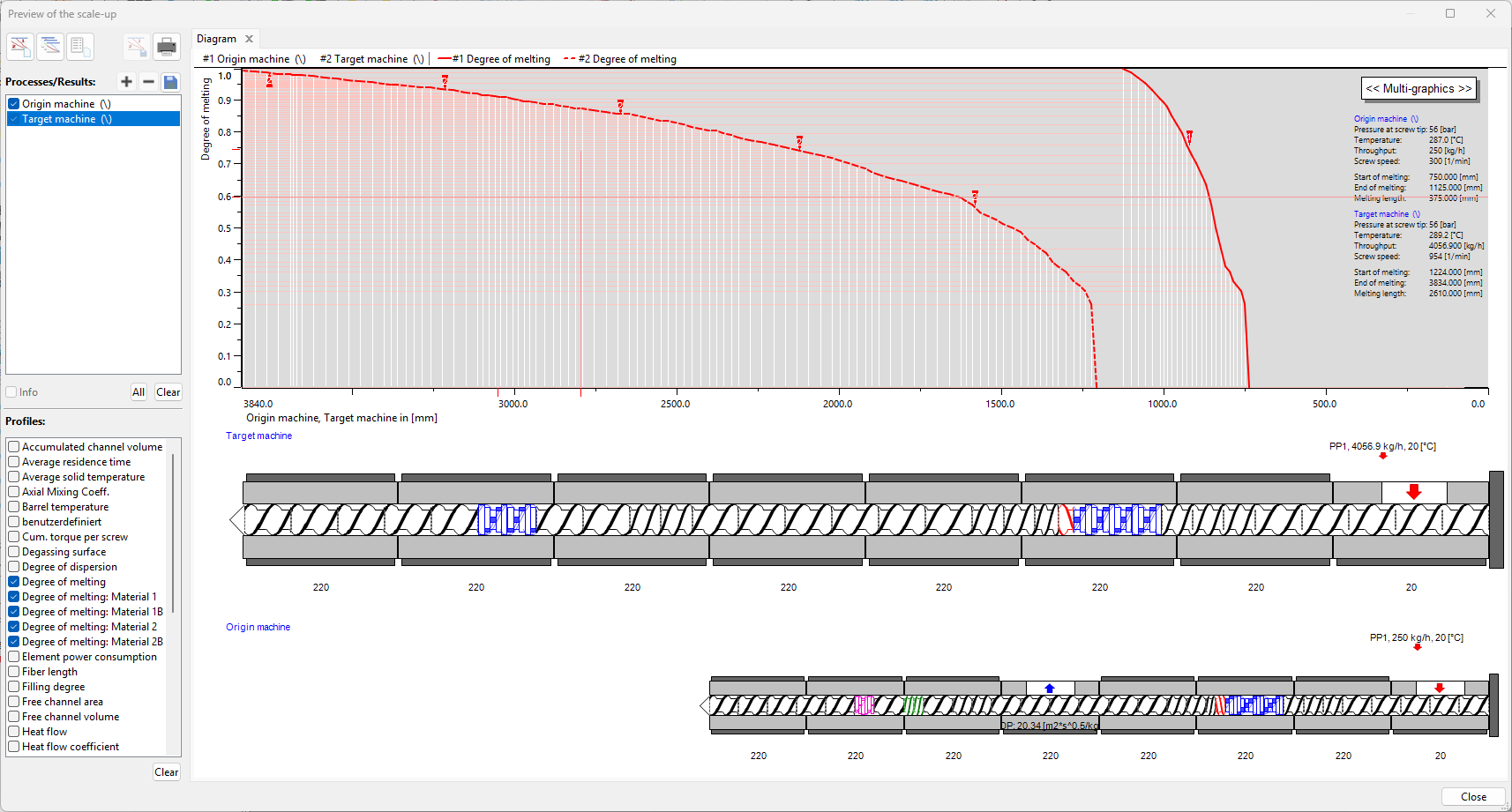
After confirming again, a preview of the simulation results is shown in a multi-graphic form (see figure). This enables a first comparison of both processes. Additionally, the operating parameters of the model design and the master design are displayed. While performing a scale-up it is possible to modify boundary conditions by means of the Back button.
Complete
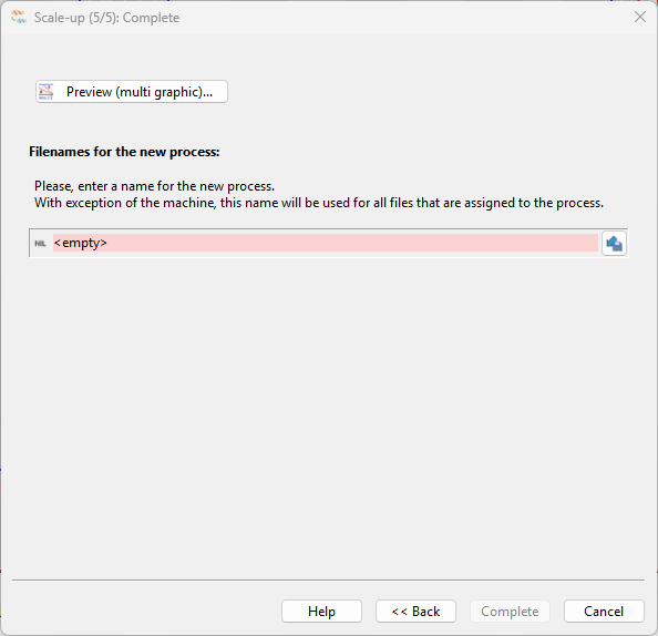
After closing the preview, the newly generated process can be saved by specifying a name and by pressing the Finish button afterwards.
The generated process is independent and can be loaded, changed and saved anew like any SIGMA process.